MPLS L3 ××× 实验一
发布时间:2019-09-16 07:34:33编辑:auto阅读(2028)
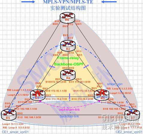
实验拓扑:
实验一说明:
配置分解(10步)
8.配置vrf的ospf sham-link;
在两边的PE上配置
1.0.0 .0/32 is subnetted, 1 subnets
3.0.0 .0/32 is subnetted, 1 subnets
20.0.0 .0/24 is subnetted, 1 subnets
7.0.0 .0/32 is subnetted, 1 subnets
10.0.0 .0/24 is subnetted, 1 subnets
12.0.0 .0/24 is subnetted, 1 subnets
13.0.0 .0/24 is subnetted, 1 subnets
1.0.0 .0/32 is subnetted, 1 subnets
3.0.0 .0/32 is subnetted, 1 subnets
20.0.0 .0/24 is subnetted, 1 subnets
7.0.0 .0/32 is subnetted, 1 subnets
10.0.0 .0/24 is subnetted, 1 subnets
12.0.0 .0/24 is subnetted, 1 subnets
13.0.0 .0/24 is subnetted, 1 subnets
实验环境:
实验一只用到拓扑中的 R1、R2、R3、R5、R7五台路由器,实验过程均使用DynamipsGUI v2.7完成。
实验一说明:
1、R1(PE1)、R2(P)、R3(PE2)为MPLS骨干区域(IGP为OSPFv2);
R4用来模拟帧中继交换机;
R1、R3 为核心边缘接入设备PE;
R5、R7为骨干网所连接的CE设备;
2、PE与CE之间均运行OSPF,CE1与CE2为同一***的两个站点,其之间是需要互通;
在PE2上,另使用两个环回口模拟两个其它的***。来测试RT的导入导出效果;
其中CE1可以接收全部***v4路由,CE2只接收CE1和另外一个***的路由,因为互访是
双向的,所以RT属性的导入导出值在互访的***上均要设置
(此实验中未实现不同***之间的单向访问)
3、在CE1和CE2之间存在一条直连串行链路,模拟backdoor用于备份,在PE1、PE2上的对应vrf中配置sham-link,并将该虚链路cost值设置为5,而backdoor两端的串口cost值调整为1600,以促使sham-link链路生效.
4、在mpls核心区域上配置链路和区域MD5认证,在CE路由器的相关area 0区域配置 MD5认证;
5、在mpls核心区域关闭TTL传输,使得ping应用时,核心对CE端不可见;
6、验证RIB、LFIB、LIB、FIB;
因配置较多,以下仅是给出连贯的思路,实验完整配置并未附加于此文内,但拓扑图是完整的.
此实验完整配置在另一篇MPLS L3 ×××实验一(配置)中
配置分解(10步)
1.配置各路由器接口并测试连通性,配置mpls 骨干区IGP(ospf)路由并测试连通性
配置用的是基础路由知识
配置用的是基础路由知识
2.配置骨干网运行mpls (只需在运行mpls的接口上启用mpls ip(LDP)
配置后在运行mpls的骨干区各路由器上
show mpls ldp neighbor // 查看LDP邻居显示,确认LDP(基于TCP连接目的端口646)均正常运行
sh mpls forwarding-table // 查看MPLS IP转发表FLIB 状态
配置后在运行mpls的骨干区各路由器上
show mpls ldp neighbor // 查看LDP邻居显示,确认LDP(基于TCP连接目的端口646)均正常运行
sh mpls forwarding-table // 查看MPLS IP转发表FLIB 状态
3.配置PE1与PE2的bgp对等,这里是配置了一个对等体组,并验证bgp邻居建立成功
配置后
sh ip bgp summary // 粗略查看BGP邻居状态是否存在
sh ip bgp nei // 查看BGP邻居是否建立成功(信息很多)
其中显示有BGP state = Established, up for 00:02:30则是建立成功了
4.在PE路由器上配置bgp路由支持mp-bgpP协议,并验证***v4地址状态
BGP默认只支持IPv4地址族,加上no bgp default ipv4-unicast 使其支持×××V4地址族,并在×××V4地址族下active
配置后show ip bgp nei //查看是否有如下显示,如有显示说明***v4地址族已激活
Neighbor capabilities:
Route refresh: advertised and received(old & new)
Address family IPv4 Unicast: advertised and received
Address family ×××v4 Unicast: advertised and received
5.在PE1和PE2上配置vrf并绑定到所属接口(物理口或自接口)
ip vrf smcat_***01 //在R1(PE1)和R3(PE2)上配置来对应CE的私网路由转发
rd 10:100
route-target export 10:100
route-target import 11:100
route-target import 12:100
route-target import 13:100
绑定vrf后,即改变了接口的从属关系,该接口原有IP 地址会被清除,需重新配置
ip vrf smcat_***01 //在R1(PE1)和R3(PE2)上配置来对应CE的私网路由转发
rd 10:100
route-target export 10:100
route-target import 11:100
route-target import 12:100
route-target import 13:100
绑定vrf后,即改变了接口的从属关系,该接口原有IP 地址会被清除,需重新配置
6.配置CE到PE之间的ospf;
在两边PE上配置
在两边PE上配置
router os 10 vrf smcat_***01 // 在PE和×××客户之间运行OSPF,这里两边vrf名字必须一致
net x.x.x.x 255.255.255.x a 0 //两边的区域必须一致,使用area 0
net x.x.x.x 255.255.255.x a 0 //两边的区域必须一致,使用area 0
7.在vrf所属ospf进程与mp-bgp之间做双向重发布;
在两边的PE上配置
在两边的PE上配置
router ospf 10 vrf smcat_***01
redistribute bgp 100 metric 10 subnets //在特定 vrf与mp-bgp之间做双向重发布
network 192.168.1.0 0.0.0.3 area 0
redistribute bgp 100 metric 10 subnets //在特定 vrf与mp-bgp之间做双向重发布
network 192.168.1.0 0.0.0.3 area 0
8.配置vrf的ospf sham-link;
在两边的PE上配置
router ospf 10 vrf smcat_***01
router-id 1.1.1.10
area 0 sham-link 1.1.1.10 3.3.3.10 cost 5
router-id 1.1.1.10
area 0 sham-link 1.1.1.10 3.3.3.10 cost 5
// 1.1.1.10这个地址必须是属于该vrf的并且必须通告进mp-bgp
interface Loopback1
ip vrf forwarding smcat_***01 //将smcat_***01这个vrf绑定到loop1接口上
ip address 1.1.1.10 255.255.255.255
router bgp 100
address-family ipv4 vrf smcat_***01
network 1.1.1.10 mask 255.255.255.255
interface Loopback1
ip vrf forwarding smcat_***01 //将smcat_***01这个vrf绑定到loop1接口上
ip address 1.1.1.10 255.255.255.255
router bgp 100
address-family ipv4 vrf smcat_***01
network 1.1.1.10 mask 255.255.255.255
//将用于sham-link连接的这个地址通告进mp-bgp中对应的ipv4 vrf里
最后要调整两CE端直连接口(串口)的开销值,
interface Serial1/2 //此处为CE1上
ip address 192.168.1.9 255.255.255.252
ip ospf cost 1600
默认为串口ospf开销值为 64, 如未调整,会出现有些路由在骨干网中的路径总开销当大于64时, 依然会在骨干网正常时走这个后门备用链路
interface Serial1/2 //此处为CE1上
ip address 192.168.1.9 255.255.255.252
ip ospf cost 1600
默认为串口ospf开销值为 64, 如未调整,会出现有些路由在骨干网中的路径总开销当大于64时, 依然会在骨干网正常时走这个后门备用链路
注:
sham-link并不是任意条件下都可简单的连接两个不连续的area,必须满足一定条件:
1> sham-link必须连接两个相同的area ,sham-link的LSA只有type-1,所以连接的两个area必须相同(用area0).
2>两个连续的area必须有一条共享的backdoor-link,没有backdoor-link的两个相同area是创建不起来sham-link链路的
3> 必须通过设置sham-link和backdoor-link的cost差异来确定ospf路由.
一般都是优先使用mpls *** 骨干传输数据,只是用vrf内的链路做备用线路
4>必须是在支持多vrf的增加了防止路由环路功能ospf下使用.
配置后用sh ip os sham-link //查看该虚链路的状态(是查看邻接关系,而不仅是端口up)
R1_PE1(config)#do sh ip os sh
Sham Link OSPF_SL0 to address 3.3.3 .10 is up
Area 0 source address 1.1.1 .10
Run as demand circuit
DoNotAge LSA allowed. Cost of using 5 State POINT_TO_POINT,
Timer intervals configured, Hello 10, Dead 40, Wait 40,
Hello due in 00:00:02
Adjacency State FULL (Hello suppressed)
Index 2/2, retransmission queue length 0, number of retransmission 0
First 0x0(0)/0x0(0) Next 0x0(0)/0x0(0)
Last retransmission scan length is 0, maximum is 0
Last retransmission scan time is 0 msec, maximum is 0 msec
R1_PE1(config)#
R3_PE2(config)#do sh ip os sh
Sham Link OSPF_SL0 to address 1.1.1 .10 is up
Area 0 source address 3.3.3 .10
Run as demand circuit
DoNotAge LSA allowed. Cost of using 5 State POINT_TO_POINT,
Timer intervals configured, Hello 10, Dead 40, Wait 40,
Hello due in 00:00:03
Adjacency State FULL (Hello suppressed)
Index 2/2, retransmission queue length 0, number of retransmission 0
First 0x0(0)/0x0(0) Next 0x0(0)/0x0(0)
Last retransmission scan length is 0, maximum is 0
Last retransmission scan time is 0 msec, maximum is 0 msec
R3_PE2(config)#
9.配置ospf骨干区域、链路认证以及CE端的ospf区域认证
配置用的是基础ospf路由知识
配置用的是基础ospf路由知识
10.关闭MPLS标签在骨干区域中的TTL传播,从而把骨干网络隐藏起来
no mpls ip propagate-ttl
是关闭所有PE(入口PE和出口PE两端)路由器上的MPLS TTL传播,不是关闭P路由器上的;
关闭后traceroute将显示经过mpls骨干只有一跳就到达出口PE上了(只能看到出口PE上的一跳了),在目的为P路由器时icmp是失效的;
方向从R7(CE2) 用源loop1 traceroute R5(CE1) 的loop1
R7_CE2(config)#do trace 10.1.1 .1 sou lo1
Type escape sequence to abort.
Tracing the route to 10.1.1 .1
1 192.168.1.6 176 msec 144 msec 144 msec
2 172.16.1.6 [MPLS: Labels 17/20 Exp 0] 384 msec 360 msec 360 msec
//R3(PE2)将数据包用标签17转发给了R1(PE1)
3 192.168.1.2 [MPLS: Label 20 Exp 0] 288 msec 288 msec 336 msec
// R1(PE1)将内层标签跳出还原数据包传给R5(CE1)
4 192.168.1.1 360 msec * 384 msec
R7_CE2(config)#
在R3(PE2)上关闭mpls 的TTL传播
R7_CE2(config)#do trace 10.1.1 .1 sou lo1
Type escape sequence to abort.
Tracing the route to 10.1.1 .1
1 192.168.1.6 148 msec 172 msec 120 msec
2 192.168.1.2 [MPLS: Label 20 Exp 0] 288 msec 312 msec 284 msec
//只有出口R1(PE1)的显示了
3 192.168.1.1 504 msec * 384 msec
R7_CE2(config)#
验证sham-link在正常工作( 以R7(CE2)端来观察 ):
当R5(CE1)和R7(CE2)之间的backdoor-link工作正常时,先显示一下R7(CE2)上当前的路由表,注意查看所有非直连路由的下一跳,之后断开CE2-> PE2的连接,模拟CE到广域网的中断(或ISP故障)造成的sham-link链路断开,此时用
clear ip route * 清除一下CE2上的路由表来重新学习这些路由,过一会再显示一下CE2上当前的路由表,此时学到的所有非直连路由的下一跳均改为了到CE1的直连backdoor-link的下一跳地址192.168.1.9,之后恢复CE1-> PE1的连接,恢复后不要手动清除CE1上的路由表, 过一会再sh ip route会发现CE2上的所有非直连路由的下一跳自动又改回了192.168.1.6
反复测试2次会发现sham-link的功能.
R7_CE2(config)#do r //断开前backdoor-link工作正常时, R7(CE2)上的路由表
Gateway of last resort is not set
O E2 1.1.1 .10 [110/10] via 192.168.1.6, 00:00:06, Serial1/0
O E2 3.3.3 .10 [110/10] via 192.168.1.6, 00:00:06, Serial1/0
C 20.1.1 .0 is directly connected, Loopback1
C 7.7.7 .7 is directly connected, Loopback0
O IA 10.1.1 .0 [110/134] via 192.168.1.6, 00:00:06, Serial1/0
O E2 12.1.1 .0 [110/10] via 192.168.1.6, 00:00:06, Serial1/0
192.168.1.0/30 is subnetted, 3 subnets
C 192.168.1.8 is directly connected, Serial1/2
O 192.168.1.0 [110/133] via 192.168.1.6, 00:00:07, Serial1/0
C 192.168.1.4 is directly connected, Serial1/0
O E2 13.1.1 .0 [110/10] via 192.168.1.6, 00:00:07, Serial1/0
R7_CE2(config)#
R7_CE2(config)#do r //断开CE2-> PE2的连接后, R7(CE2)上的路由表
Gateway of last resort is not set
O E2 1.1.1 .10 [110/10] via 192.168.1.9, 00:00:55, Serial1/2
O E2 3.3.3 .10 [110/10] via 192.168.1.9, 00:00:10, Serial1/2
C 20.1.1 .0 is directly connected, Loopback1
C 7.7.7 .7 is directly connected, Loopback0
O IA 10.1.1 .0 [110/1601] via 192.168.1.9, 00:00:55, Serial1/2
O E2 12.1.1 .0 [110/10] via 192.168.1.9, 00:00:10, Serial1/2
192.168.1.0/30 is subnetted, 3 subnets
C 192.168.1.8 is directly connected, Serial1/2
O 192.168.1.0 [110/1664] via 192.168.1.9, 00:00:57, Serial1/2
C 192.168.1.4 is directly connected, Serial1/0
O E2 13.1.1 .0 [110/10] via 192.168.1.9, 00:00:11, Serial1/2
R7_CE2(config)#
最后测试验证 (主要是查看四个库):
sh ip route RIB
sh mpls ldp bind LIB
sh ip cef [x.x.x.x] FIB
sh mpls forwarding-table LFIB
#sh ip route // 在两端CE上查看是否已学到对端站点的×××路由信息
#sh ip rou vrf smcat_***01 // 在两端PE上查看VRF的路由表中是否正确学到了应该学到的路由
#ping vrf smcat_***01 x.x.x.x //在两端PE上验证到对端的VRF(两×××客户之间)是否能ping通
#sh mpls ldp binding //在核心路由器上查看标签绑定对应关系,每条IGP路由都有一个local本地标签和从所有的mp-bgp邻居分配的标签;
#sh ip rou vrf smcat_***01 // 在两端PE上查看VRF的路由表中是否正确学到了应该学到的路由
#ping vrf smcat_***01 x.x.x.x //在两端PE上验证到对端的VRF(两×××客户之间)是否能ping通
#sh mpls ldp binding //在核心路由器上查看标签绑定对应关系,每条IGP路由都有一个local本地标签和从所有的mp-bgp邻居分配的标签;
R1_PE1#sh mpls ldp bin //这里就是LIB,显示的是外层公网标签,不涉及任何私网标签
tib entry: 1.1.1.1/32, rev 2
local binding: tag: imp-null
remote binding: tsr: 2.2.2.2:0, tag: 17
tib entry: 2.2.2.2/32, rev 10
local binding: tag: 17
remote binding: tsr: 2.2.2.2:0, tag: imp-null
tib entry: 3.3.3.3/32, rev 16
local binding: tag: 18
remote binding: tsr: 2.2.2.2:0, tag: 16
tib entry: 172.16.1.0/30, rev 6
local binding: tag: imp-null
remote binding: tsr: 2.2.2.2:0, tag: imp-null
tib entry: 172.16.1.4/30, rev 4
local binding: tag: 16
remote binding: tsr: 2.2.2.2:0, tag: imp-null
R1_PE1#
#sh mpls fording //同时对应着检验LFIB中标签交换的过程;
R1_PE1#sh mpls for // R1(PE1)上的LFIB,即MPLS IP转发表,是根据FIB+LIB生成的.
Local Outgoing Prefix Bytes tag Outgoing Next Hop
tag tag or VC or Tunnel Id switched interface
16 Pop tag 172.16.1.4/30 0 Se1/0 point2point
17 Pop tag 2.2.2.2/32 0 Se1/0 point2point
18 16 3.3.3.3/32 0 Se1/0 point2point
20 Aggregate 192.168.1.0/30[V] 3808
22 Untagged 10.1.1.0/24[V] 0 Se1/3 point2point
24 Aggregate 1.1.1.10/32[V] 20788
25 Untagged 192.168.1.8/30[V] 0 Se1/3 point2point
R1_PE1#
R1_PE1#sh ip bgp ***v all la // 在两边的PE上查看mp-bgp ***v4路由的私网标签分配.
Network Next Hop In label/Out label
Route Distinguisher: 10:100 (smcat_***01)
1.1.1.10/32 0.0.0.0 24/aggregate(smcat_***01)
Network Next Hop In label/Out label
Route Distinguisher: 10:100 (smcat_***01)
1.1.1.10/32 0.0.0.0 24/aggregate(smcat_***01)
//此处显示的标签就是mp-bgp分配的内层私网标签,外层标签已在倒数第二跳弹出了
其中0.0.0 .0的是自己始发的标签
3.3.3.10/32 3.3.3.3 nolabel/19
10.1.1.0/24 192.168.1.1 22/nolabel
12.1.1.0/24 3.3.3.3 nolabel/25
13.1.1.0/24 3.3.3.3 nolabel/26
20.1.1.1/32 3.3.3.3 nolabel/22
192.168.1.0/30 0.0.0.0 20/aggregate(smcat_***01)
192.168.1.4/30 3.3.3.3 nolabel/23
192.168.1.8/30 3.3.3.3 25/20
192.168.1.1 25/nolabel
Route Distinguisher: 11:100
3.3.3.10/32 3.3.3.3 nolabel/19
20.1.1.1/32 3.3.3.3 nolabel/22
192.168.1.4/30 3.3.3.3 nolabel/23
192.168.1.8/30 3.3.3.3 nolabel/20
Route Distinguisher: 12:100
12.1.1.0/24 3.3.3.3 nolabel/25
Route Distinguisher: 13:100
13.1.1.0/24 3.3.3.3 nolabel/26
R1_PE1#
[待续]
上一篇: python 分析Google音乐下载地
下一篇: solaris学习3:启动过程
- openvpn linux客户端使用
50552
- H3C基本命令大全
49871
- openvpn windows客户端使用
40461
- H3C IRF原理及 配置
37451
- Python exit()函数
31884
- openvpn mac客户端使用
28765
- python全系列官方中文文档
27683
- 1.常用turtle功能函数
22466
- python 获取网卡实时流量
22461
- python 获取Linux和Windows硬件信息
20774
- Python搭建一个RAG系统(分片/检索/召回/重排序/生成)
559°
- Browser-use:智能浏览器自动化(Web-Agent)
1183°
- 使用 LangChain 实现本地 Agent
964°
- 使用 LangChain 构建本地 RAG 应用
890°
- 使用LLaMA-Factory微调大模型的function calling能力
1149°
- 复现一个简单Agent系统
1005°
- LLaMA Factory-Lora微调实现声控语音多轮问答对话-1
1630°
- LLaMA Factory微调后的模型合并导出和部署-4
3021°
- LLaMA Factory微调模型的各种参数怎么设置-3
2740°
- LLaMA Factory构建高质量数据集-2
2065°
- 姓名:Run
- 职业:谜
- 邮箱:383697894@qq.com
- 定位:上海 · 松江
